Raspberry Pi
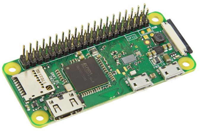
Raspberry Pi Zero W
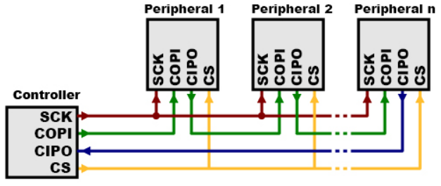
SPI
Full duplex serial interface bus with seperated clock and dataline along with a select line.
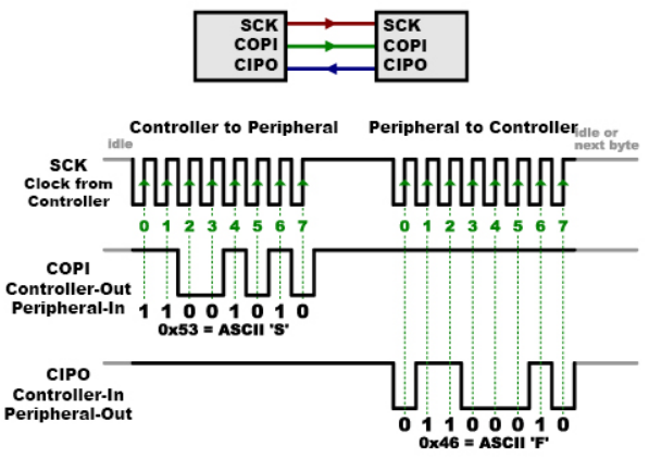
When data is sent from the controller to a peripheral, it's sent on a
data line called COPI, for "Controller Out / Peripheral In".
If the peripheral needs to send a response back to the controller, the
controller will continue to generate a prearranged number of clock
cycles,
and the peripheral will put the data onto a third data line called CIPO, for "Controller In / Peripheral Out".
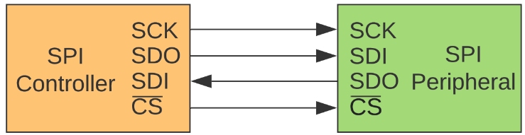
MOSI - Master Out Slave In -> SDO - Serial Data Out
MISO - Master In Slave Out -> SDI - Serial Data In
SS - Slave Select -> CS Chip Select
MOMI - Master Out Master In -> COPI Controller Out/Controller In
SOSI - Slave Out Slave In -> CIPO Controller Out Peripheral In
SDIO - Serial Data In/Out
SCK/CLK/SLC - Serial Clock (generated by the controller/master)
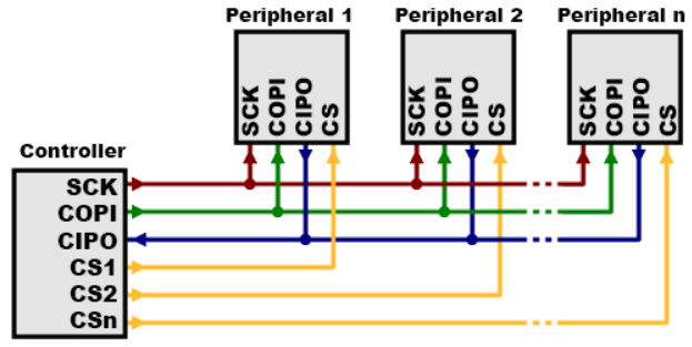
Using multiple SPI devices by seperate CS for each
Using mutple daisychained SPI output only devices like LED
Back